The best way to think of this is that for a given depth of wheel, they are all going to have really similar surface areas... so the amount of total force that has to be resolved is going to be somewhat similar. This is how the whole Firecrest thing came about... once we had deep wheels that could output drag numbers nearly identical to a disc, we believed that there would be little more speed to be found, but that we should focus on handling as the real problem with deep wheels was that in the conditions where they were most advantageous to run (in the wind) people didn't want to ride them.. So all of the surface of the wheel has some forces on it, the question is how do you resolve and distribute them to minimize drag, side force and steering torque. Ultimately we learned that it becomes a bit of a shell game where every possible solution has some tradeoff and once the system is highly optimized the tradeoffs generally become nearly 1:1 where 10 grams of drag reduction just becomes 10 grams of side force, etc..
I don't have access to all my old Zipp stuff, but here's a link to a presentation
Matt Godo gave in 2011 using our 2009-2010 benchmarking study for Firecrest.. there are other presentations that show not only steering torque (he called it turning moment) but wattage to spin as well as the transient effects of turbulent and vortex shedding. Also shown here but only minimally are the visualization tools we developed to understand where on the wheels the forces were acting which allowed the calculations of steering torques and centers of pressure (Cp) which we determined to be the biggest factor in handling.
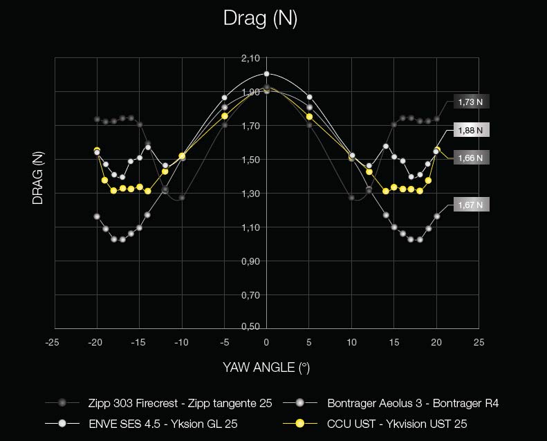
Once you eliminate the low hanging fruit of big pressure drags related to separations of flow, the only way left to sufficiently lower the drag further is to utilize aerodynamic forces have to be turned into a combination of side lift and forward lift.. The goal with Firecrest was to balance the front and rear half of the wheel so that the center of pressure remained in front of the steering axis at all angles with little fore-aft movement. You see on the graph that a front disc wheel and our own 1080 have a rearward center of pressure..and while this 'rudder effect' seems initially like a self stabilizing feature, it isn't. This is due to the way a bicycle initiates a turn.. for a bicycle to turn left, the contact patch has to move to the right, so the wheel initially has to turn right which then makes the bike lean left... this is why you fall over when you get pinned up against a curb or in a rut, you can't lean away from the curb because the wheel needs to go in the curb direction to move the contact patch to allow you to lean the other way.
Similarly, we found with the wheels..if a wheel turns into a gust wind (sounds like a good idea) the contact patch moves toward the wind, but the rider lean then goes the other way which pushes the bike/rider system along the direction of the wind and the only way to correct it is a pretty significant steer into the lean direction to move the contact patch to the other side... with Cp in front of the steering axis, a gust of wind initiates a lean/turn back into the wind.. it's much more stable.
So the problem turns out that some wheel designs, particularly ones that have sharper inner diameters is that the center of pressure will cross the steering axis at some angle..as you have larger movements of Cp with yaw in these designs. Cp crossing the steering axis means that the wheel behaves one way in certain conditions and the opposite way in other conditions, and that's even worse than just having Cp on the wrong side of the axis.. One way around this would be to have the Cp start well ahead of steering axis and then come back with yaw..this would give you proportionally higher torque values at low yaw, but at least the handling would be predictable..

Here's a Cp plot we did for the 808 with Intelligent light...sorry, I'm limited to public domain stuff, but we had hundreds of these plots and graphs showing different rim shapes and the movements of the Cp's...it's super interesting stuff! Anyway, you can see that we designed for a Cp that was as low as possible and as close to the steering axis as possible without crossing it. The Cp moving rearward with yaw means that as side force increases the lever arm relative to steering axis is decreasing.. still looking for the graphs on this, but the goal is a graph that has pretty flat steering torque regardless of wind angle.
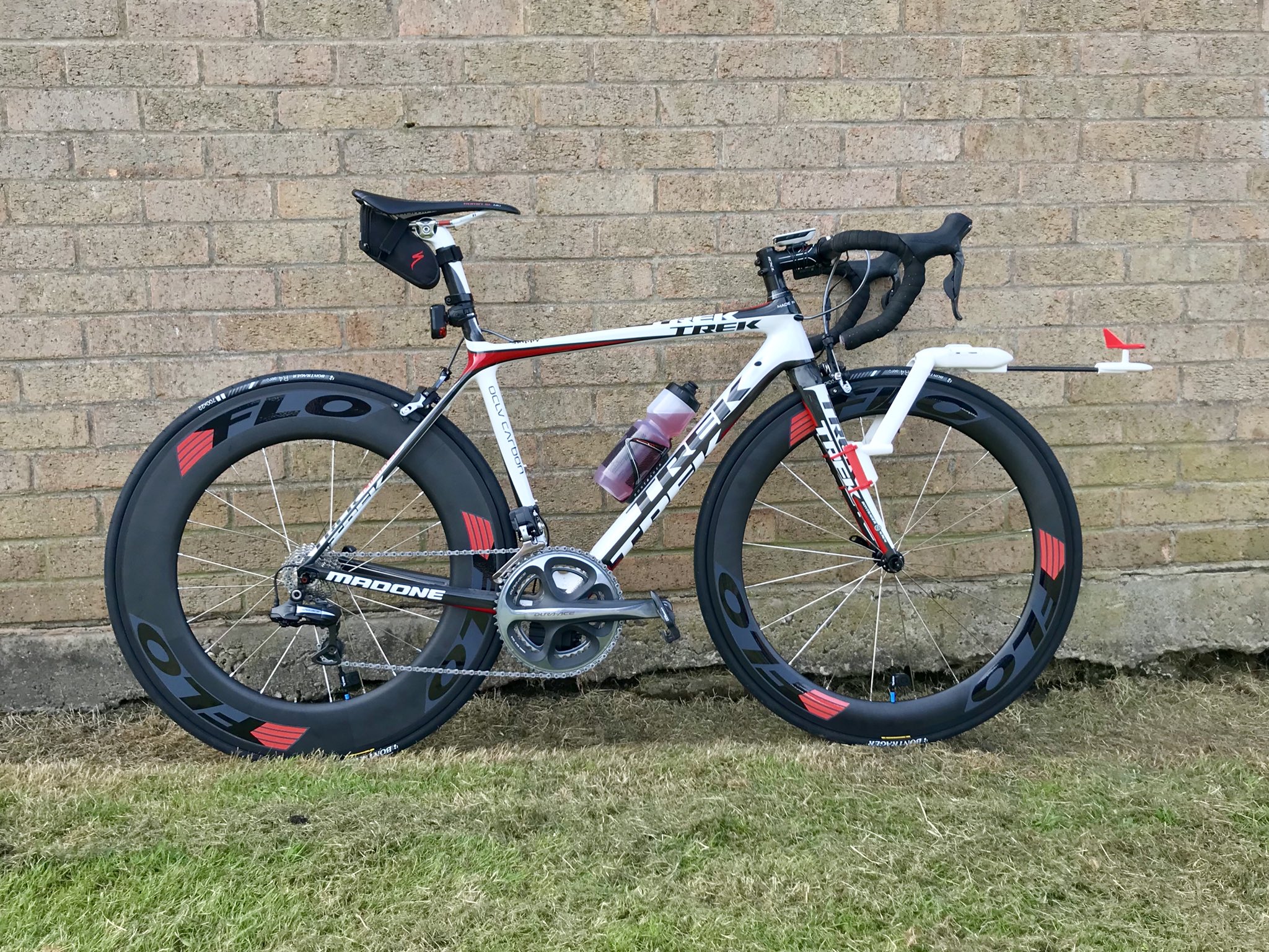
Long story short, the 808 in the Hambini test is now an ~8 year old shape...I have no doubt that there are faster shapes and designs at this depth. Heck, we had identified dozens of them before I left Zipp at the end of 2013.. but we never found one that was worth the tradeoff in handling, which is not in any way meant to say that it isn't possible. We were also beginning the study of the waveform inner diameter rims when I left and that more than tripled the design elements in a rim opening even more options for tuning. On a separate pathway we had begun using a mathematical technique called simulated annealing to seek other possible solutions for this when I left, which showed that for a given optimization parameter, there were groupings of solution sets that were competitive, but at the same time, the solution pathway we were one was pretty robust and hadn't been fully explored. Sadly you need infinite resources for that!!
http://www.SILCA.cc Check out my podcast, inside stories from more than 20 years of product and tech innovation from inside the Pro Peloton and Pro Triathlon worlds!
http://www.marginalgainspodcast.cc