P5 - Di2 9070 Brake Shifter Hack
There are plenty of posts covering the original Di2 7970 P5 brake shifter hack. I originally built my P5 up this way and things were working great.
You might ask why would you do this vs using the straight ST-9071 Shifter or using the cheaper climbing Di2 E-tube shifter?
1. I have the P5-Six and I wanted to keep my hydraulic shifting.
2. If you use a different solution, you loose the ability to program the firmware correctly. Using this solution, the E-tube software thinks you have the standard ST-9071 levers installed and will allow you to update and change all of the standard functions. Also, if you use the SW-R600, you can only hack the RD.
Here is how I installed everything. If you have any questions let me know!!
Key Parts needed:
Key Tools needed:
Specific Components/E-tube wire Lengths for those interested in upgrading their P5
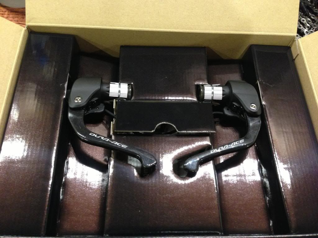
Unboxing the ST-9071 Levers:
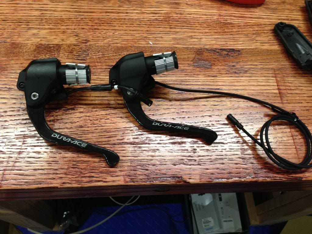
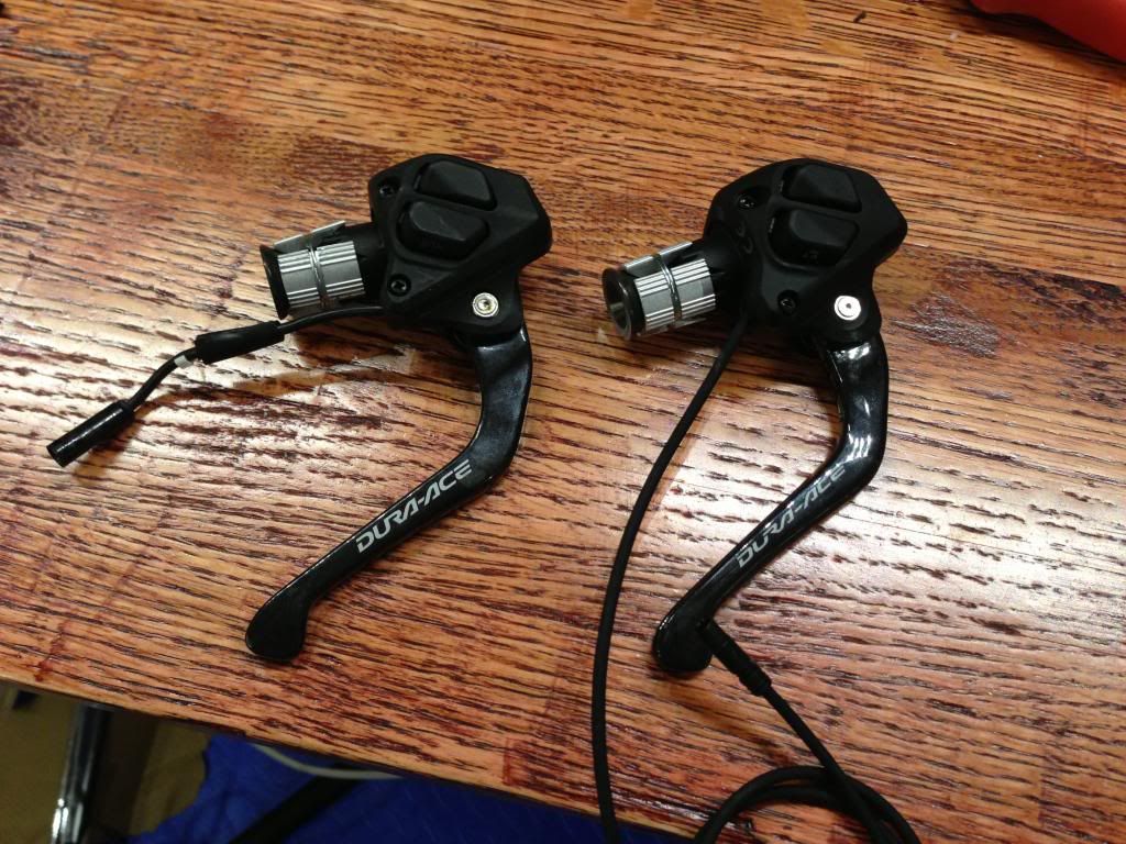
Old 7970 vs new 9070 - These are the exact same brake lever, just with a different electronic switch attachment
Begin Disassembly:
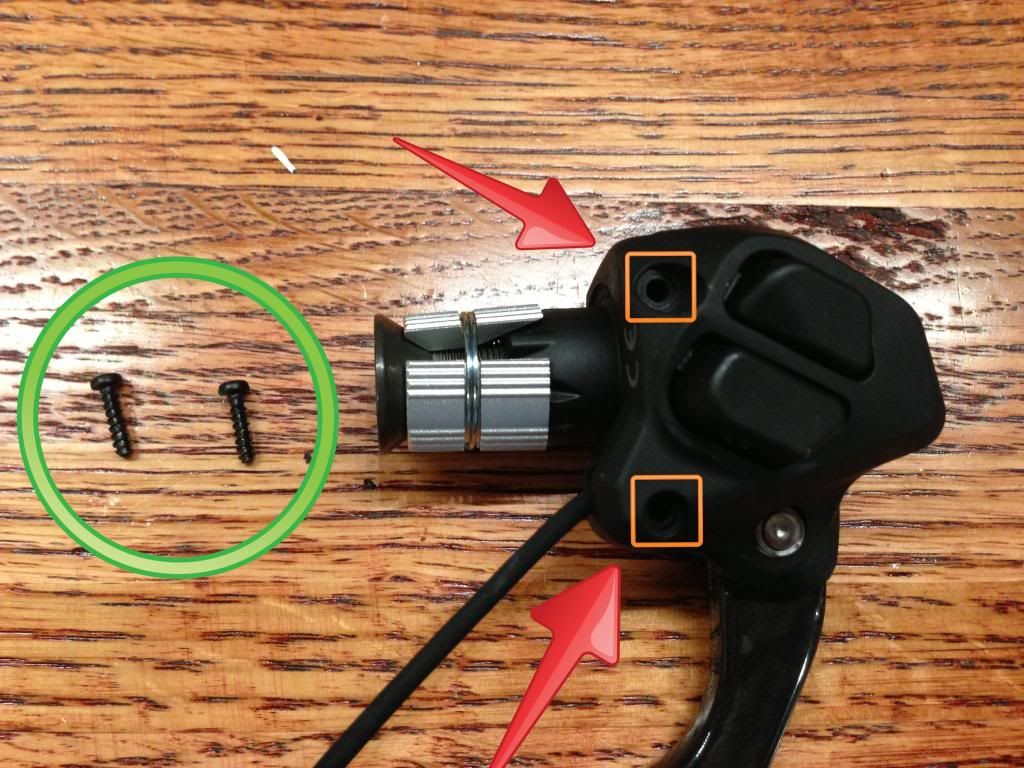
Remove the two black phillips screws:
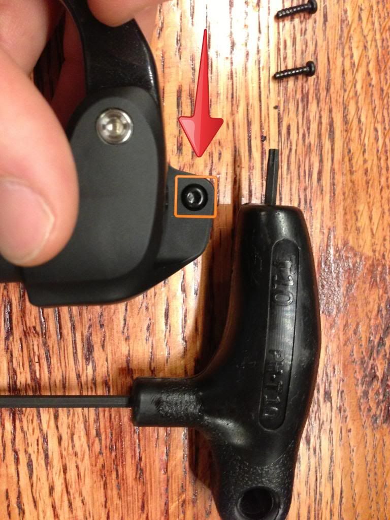
Flip the lever over and remove the #10 Torx Screw:
The Button cover will pop open like this:
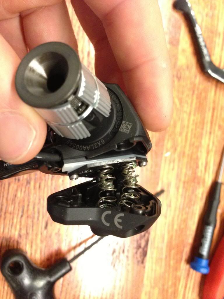
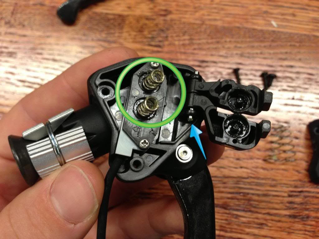
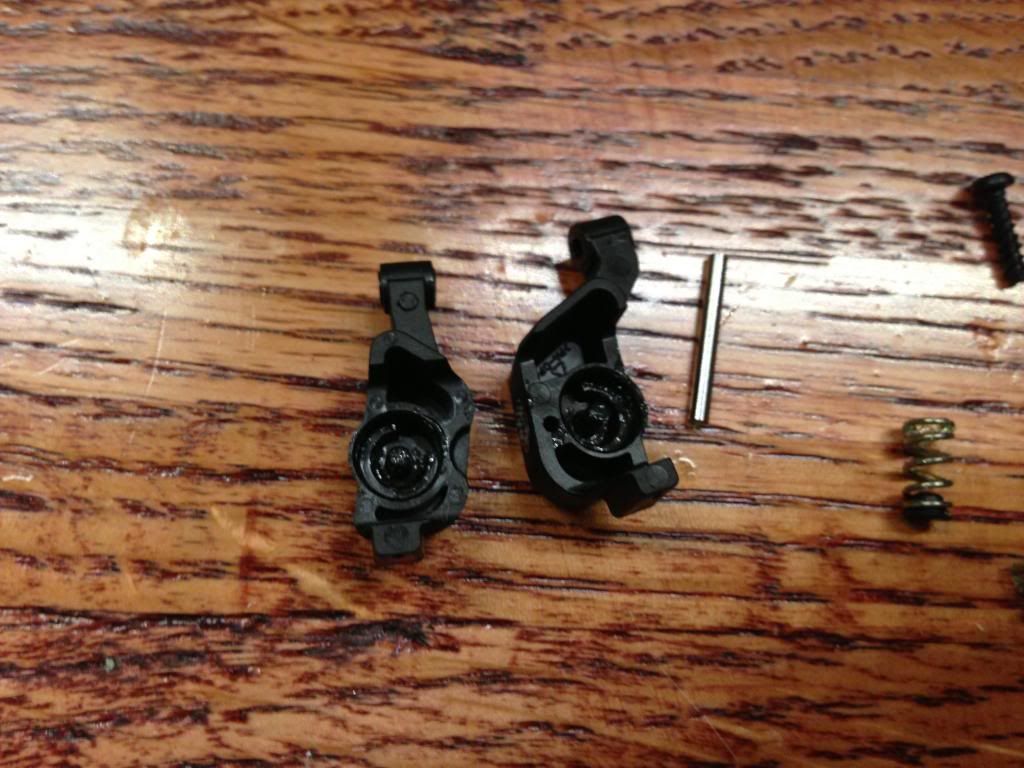
Remove the outer cover and large springs:
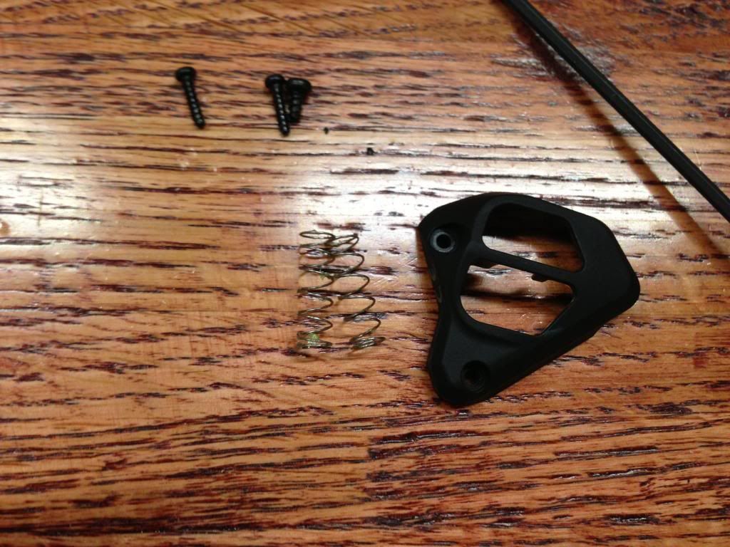
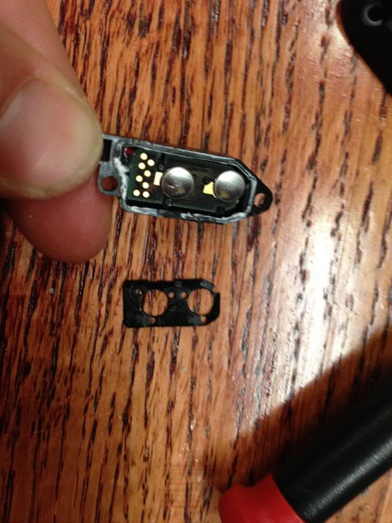
Remove the inner springs (green circle), they have a plastic piece inside the spring that holds it to the inner button, so just give them a tug to separate the two.
Also, slide the silver rod (blue arrow) out and the outer button covers will come off.
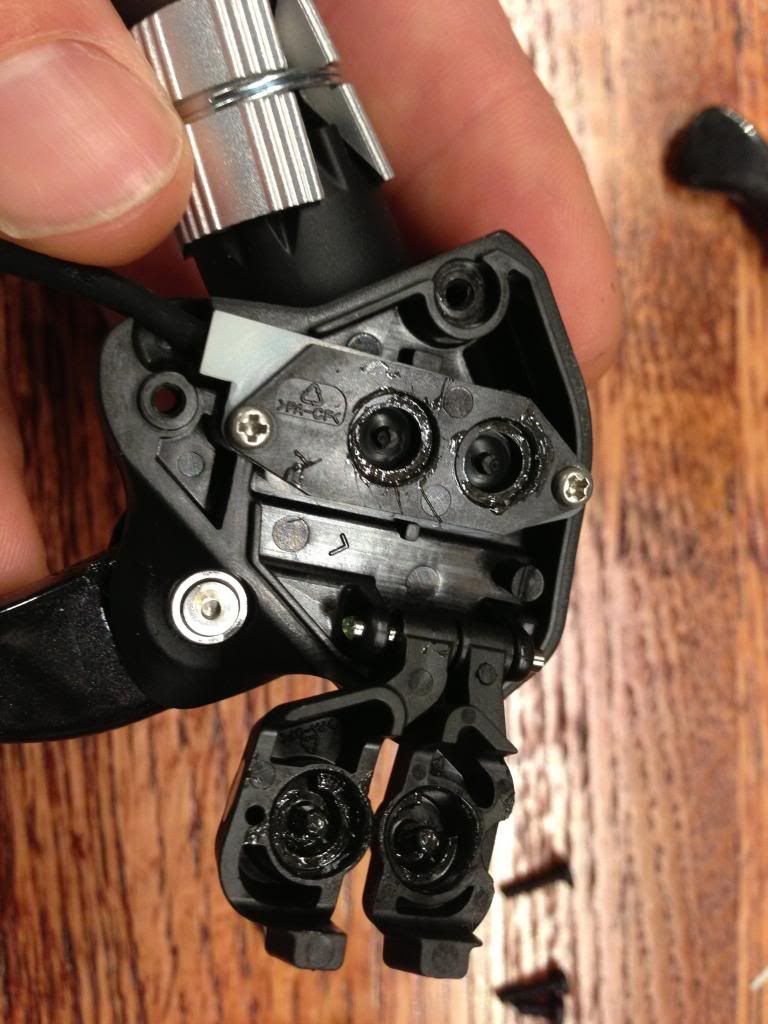
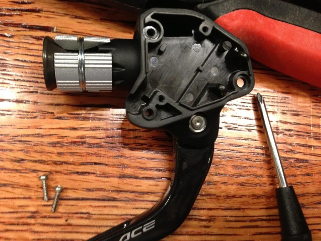
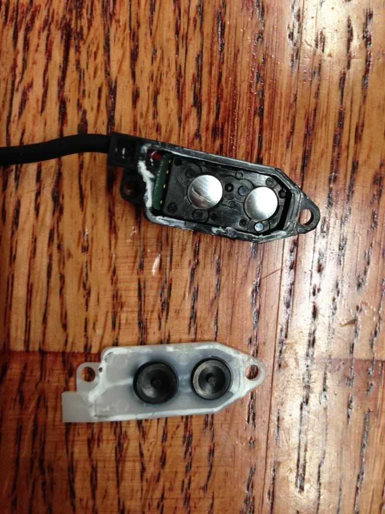
Remove the two silver phillips screws and take off the electronic shifting buttons:
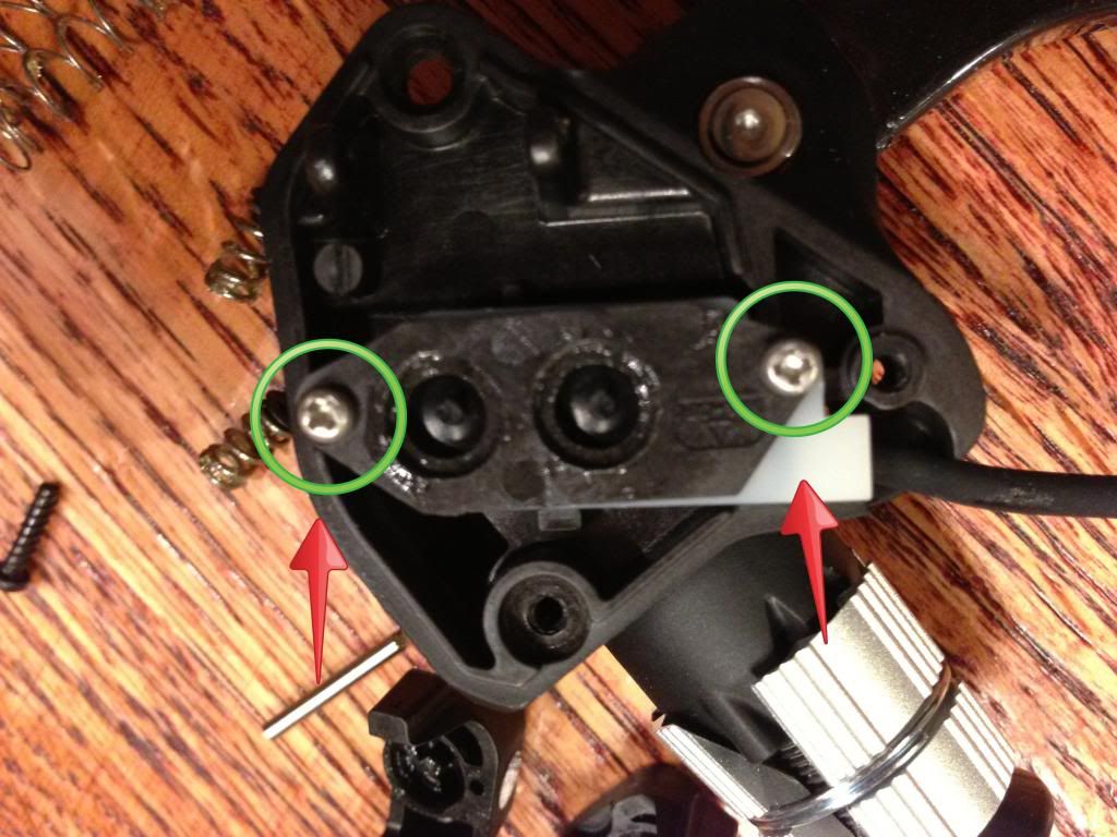
The black piece on the left will come right off, the white piece on the right is what you will work with.
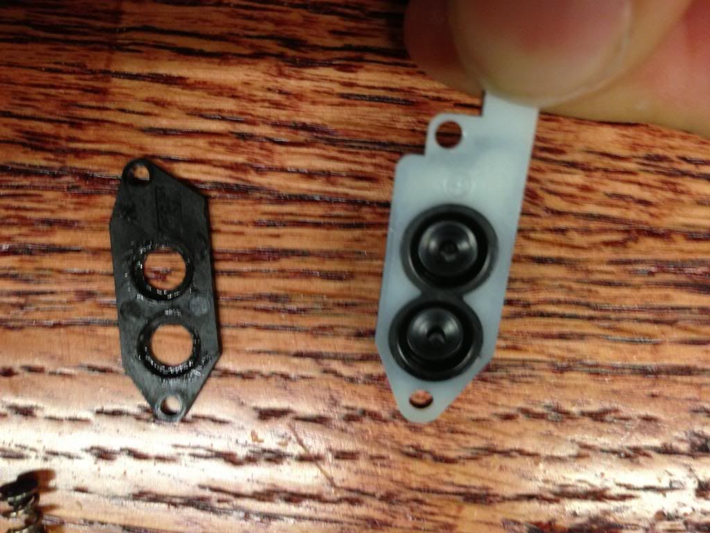
Carefully pry the white piece off of the device. It is glued on there. I used a utility knife to do this. You really won't hurt anything if you break the white piece while doing this, but it makes it cleaner if you can get the whole thing off the button system.
After it comes off:
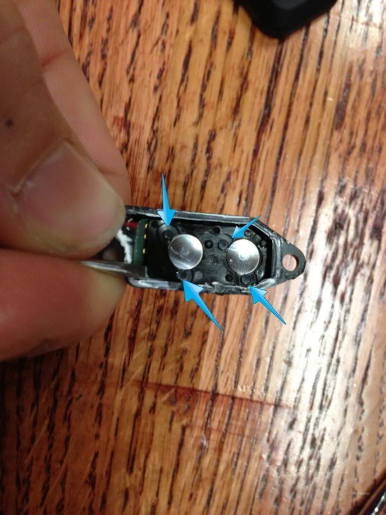
Next use a small flat screw driver to separate the plastic piece of black plastic off the circuit board. It is held on by the four posts that the blue arrows point at. This piece is worthless and might break, but don't worry about it. Just be careful of the circuit board underneath.
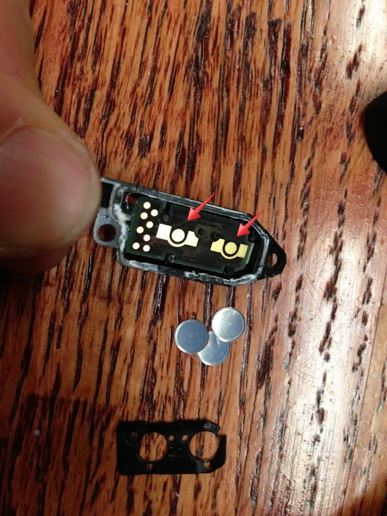
Next, dump the little silver buttons off the circuit board, they were held there by the black piece you just removed, so they will fall right off.
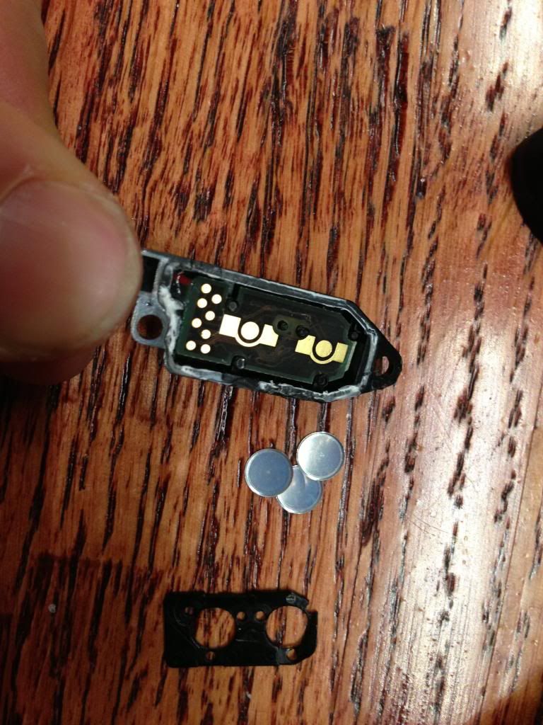
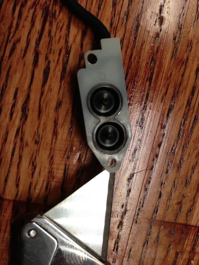
Note the contacts that the red arrows point to, these are what you will be soldering your button to.
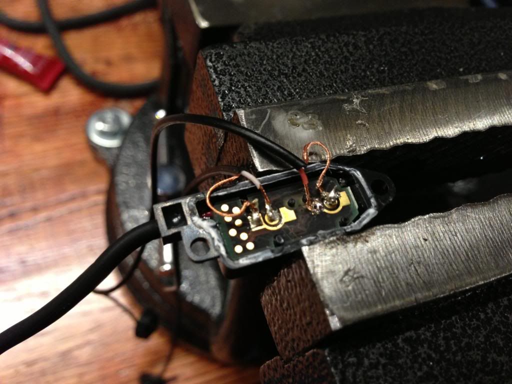
After the fact, I realized that I forgot to include photos of stripping to the wires of the buttons, but it is pretty simple. I cut of the connector, peeled apart the wires, and used my teeth to strip the wire. Here is the post solder photo. One button per contact.
***Note - Any moment switch will work here. Also the wires can be soldered either way. If you look close I accidentally did the two buttons different here.
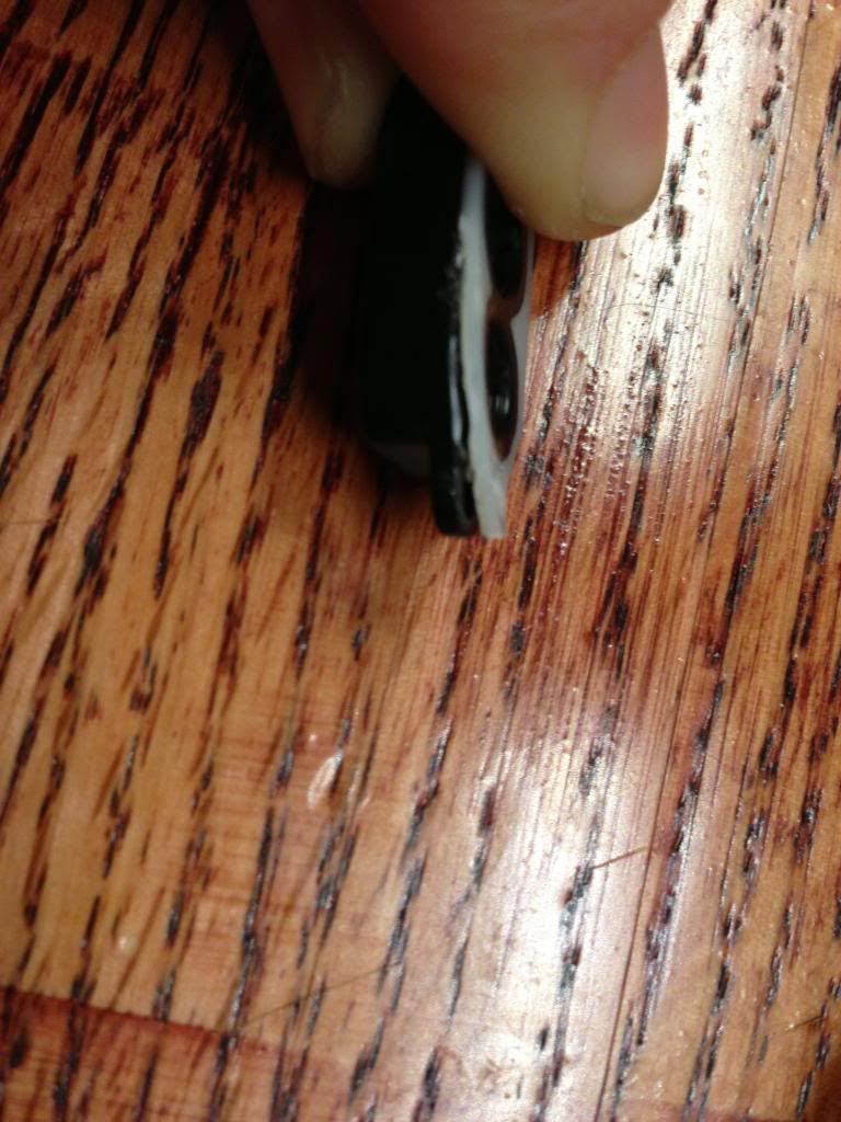
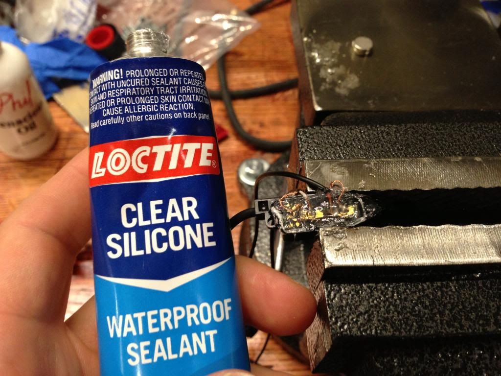
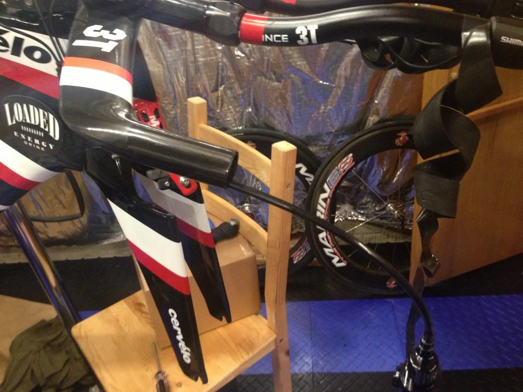
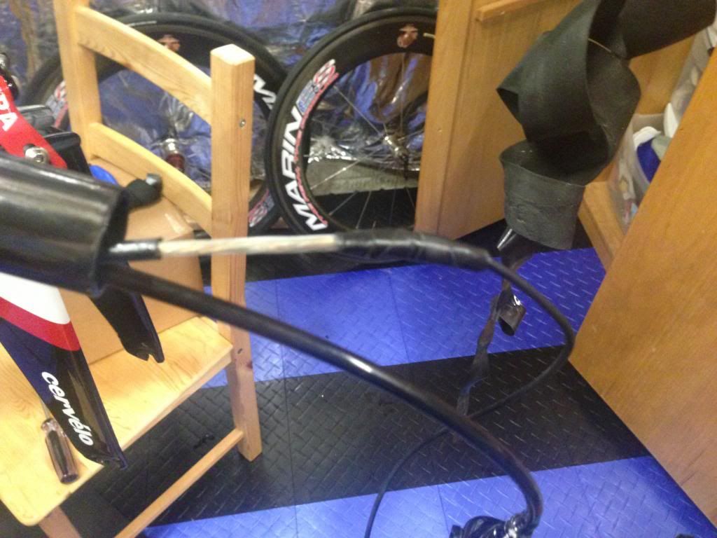
Weather sealed:
Wrapped in Electrical tape to keep it safe.
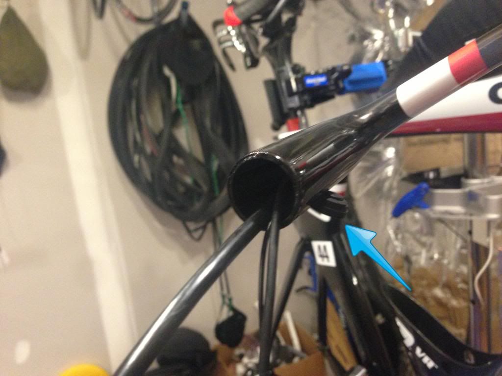
I hate how hard it is to route the cables through the drop bar, but today it went pretty smooth. I pulled out the brake lever.
Fished the wire through:
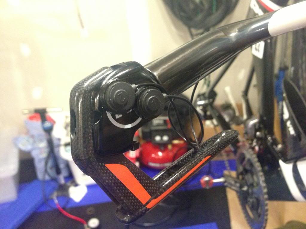
Removed the back from the button, and slid it through the cable hole.
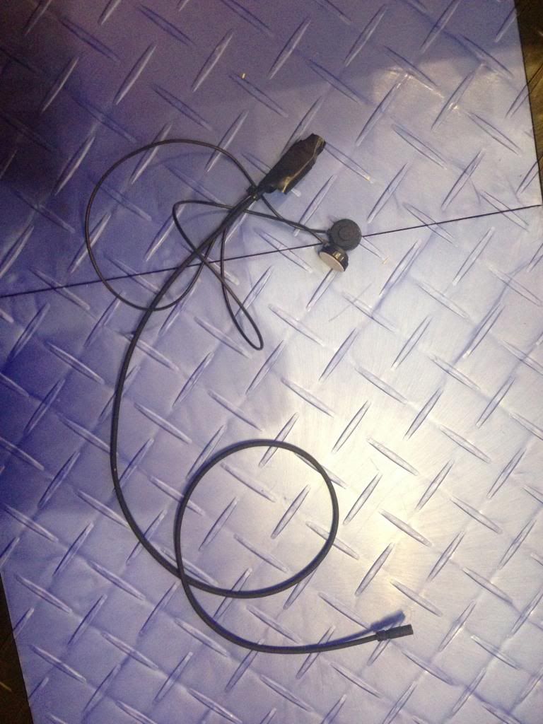
Buttons attached!!
There are plenty of posts covering the original Di2 7970 P5 brake shifter hack. I originally built my P5 up this way and things were working great.
You might ask why would you do this vs using the straight ST-9071 Shifter or using the cheaper climbing Di2 E-tube shifter?
1. I have the P5-Six and I wanted to keep my hydraulic shifting.
2. If you use a different solution, you loose the ability to program the firmware correctly. Using this solution, the E-tube software thinks you have the standard ST-9071 levers installed and will allow you to update and change all of the standard functions. Also, if you use the SW-R600, you can only hack the RD.
Here is how I installed everything. If you have any questions let me know!!
Key Parts needed:
- Di2 E-tube components (FD/RD etc)
- 5 Port Junction A Box
- ST-9071 Brake/Shifters (Dura Ace)
- 2 x Cateye Remote Button Kits - http://www.performancebike.com/bikes/Product_10052_10551_1063043_-1_400128__400128
- Zip Ties
- Silicone Filler (I used loctite)
Key Tools needed:
- Metric Allen Wrenches
- Small Phillips Screw Driver
- Small Flat Tip Screw Driver
- T10 Torx Wrench
- 8mm Wrench
- Soldering Iron/Solder
- Vice or small parts holder to hold the parts while soldering
- Favorite wire/tool to fish cables
Specific Components/E-tube wire Lengths for those interested in upgrading their P5
- Downtube Cable: 1000mm
- Battery Cable: 300mm
- FD Cable: 300mm
- RD Cable: 600mm
- Junction B Box: Internal - SM-JC41
- Junction A Box: 5 Port - SW-EW90B
- Bar End Shifters: SW-R671
- Brake Lever Shifters: ST-9071
- Short Ext Battery Mount: SM-BMR1-S
Unboxing the ST-9071 Levers:
Old 7970 vs new 9070 - These are the exact same brake lever, just with a different electronic switch attachment
Begin Disassembly:
Remove the two black phillips screws:
Flip the lever over and remove the #10 Torx Screw:
The Button cover will pop open like this:
Remove the outer cover and large springs:
Remove the inner springs (green circle), they have a plastic piece inside the spring that holds it to the inner button, so just give them a tug to separate the two.
Also, slide the silver rod (blue arrow) out and the outer button covers will come off.
Remove the two silver phillips screws and take off the electronic shifting buttons:
The black piece on the left will come right off, the white piece on the right is what you will work with.
Carefully pry the white piece off of the device. It is glued on there. I used a utility knife to do this. You really won't hurt anything if you break the white piece while doing this, but it makes it cleaner if you can get the whole thing off the button system.
After it comes off:
Next use a small flat screw driver to separate the plastic piece of black plastic off the circuit board. It is held on by the four posts that the blue arrows point at. This piece is worthless and might break, but don't worry about it. Just be careful of the circuit board underneath.
Next, dump the little silver buttons off the circuit board, they were held there by the black piece you just removed, so they will fall right off.
Note the contacts that the red arrows point to, these are what you will be soldering your button to.
After the fact, I realized that I forgot to include photos of stripping to the wires of the buttons, but it is pretty simple. I cut of the connector, peeled apart the wires, and used my teeth to strip the wire. Here is the post solder photo. One button per contact.
***Note - Any moment switch will work here. Also the wires can be soldered either way. If you look close I accidentally did the two buttons different here.
Weather sealed:
Wrapped in Electrical tape to keep it safe.
I hate how hard it is to route the cables through the drop bar, but today it went pretty smooth. I pulled out the brake lever.
Fished the wire through:
Removed the back from the button, and slid it through the cable hole.
Buttons attached!!