Aero Sensors: A Sometimes Overlooked Design Challenge

My first business was making hardware for aero testing. Just like many devices now, we had a pressure sensor to measure wind speed. We went to a wind tunnel to validate our system and ended up running into this one challenge we couldn’t overcome. We eventually removed the sensor and switched to a software only solution, to be used in an indoor velodrome.

When I worked at Specialized there was a phase were I had a company a month reaching out to me claiming to have finally solved outdoor aero testing, by adding a wind speed sensor of various designs. With all of them I shared the number one technical challenge I saw for them to solve, and I haven’t seen anybody solve it yet. If you know of a company that has this figured out, let me know, I’d love to meet them.

Heres the issue:
The presence of the rider locally affects the air flow. Depending on the location of the wind speed sensor, it could read speeds lower or higher than the freestream speed. How much you can see in the image below


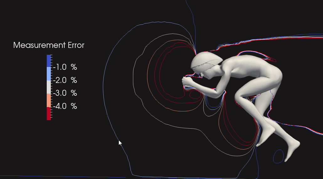
The red line closest to the rider surrounds the area where the sensor would be off by 5%. The next line shows an error of 4% and so on, the last blue line, highlighted by my mouse cursor shows how far away from the rider you would have to place the sensor to incur an error of less than 1%.

Now these sensors are being used on planes and F1 cars successfully, and the solution is to calibrate it to account for the presence of the vehicle. But here is the catch:
The main thing we want to use the data for is to inform bike fit decisions, so we want to be able to move the athlete around. But moving the athlete, also moves the “upstream pressure bubble”.


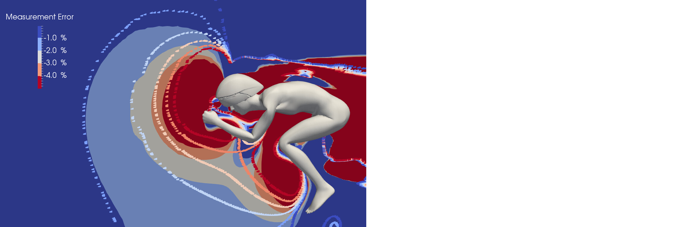
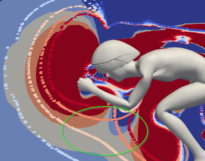
This image shows the same outlines again, but as shaded areas. What I did, was load in the wind speed data from another bike position as well, and visualized those outlines through colored dots.

For many of the most common sensor locations, you can see that the difference in wind speed measurement can be as high as 4% and is often higher than 1%. This means that our change in athlete position caused a change in wind speed measurement, that goes into our CdA/Aero calculation. A 1% error in wind speed would translate to roughly a 3% error in CdA calculation, or 6ish counts, bigger than the difference between many fit changes we want to tell apart.

What is bad is that this error source is perfectly confounded with what we want to measure, so more repeats don’t help and there is no easy way to tell if a change in measured CdA comes from improved aerodynamics or from moving the low speed air zone more over the speed sensor.

Do you know of any company that has solved this issue? How did they do it?

UPDATE: Based on @marcag s feedback I checked out Aero Sensor and their approach. I think its a good practical solution in even and relatively low wind conditions. Thanks!

6 Likes

In an indoor velodrome you may run into a similar problem, where is the center of pressure in the turns? (I do not know the correct English expression, I mean the trajectory of the point in space where the aero drag force act’s on)

This may be way off because I am in no way an aerodynamics person, but if one used the virtual elevation method of Chung would that not help solve the confound? Could that not be evaluated over various scenarios and maybe be part of the software solution to your problem? Just curious, since it seems from what I have read from Dr. Chung and others on here the method is rather precise. Just a curiosity question to help me understand the problem better.

Is the error consistent ?

All the commercial brands solve this with varying degrees of sophistication. The most simplistic versions do it in their calibration process. The sophistication of the mechanism is what thing that differentiates the various sensors. Barney from aerosensor explains his method in recent podcasts

Not sure why the thread says they all got it wrong unless you understand how they all did it.

3 Likes

In the original formalism of Chung (R. Chung, indirect estimation of CdA using a power meter, 2007) a single value for velocity enters at various places in the equation of motion. However, for example in the expression for the power to overcome air resistance there should enter the velocity quadratic of the center of pressure multiplied by the velocity of the center of gravity. It is important to measure these velocities precisely, I think it is even more important than to measure power precisely. In a velodrome the deviations of these velocities in the curves may become significant.

But velocity as I understand the equation is ground velocity not air velocity? So if you have accurate ground velocity etc or at least precise measurements then the Chung method remains precise. In this case the precision seems to me to be the big thing, accuracy not so much? So as long as the Chung measurement remains precise then the variation of air speed caused by the movement of the frontal wave should be something one could tease out since that change has no impact on the Chung result?

Entering ground velocity at any place in the equation is a simplification. This simplification is justified if banking is not high.
In mechanics forces and velocities are vectors. One may represent (rigid) bodies by specific points where the specific force vectors act. The vector of aerodynamic drag at the center of pressure (or drag), gravity at the center of gravity etc…
(Still a simplification, but I don’t want to go into vector fields or tensor fields or potential fields …. :astonished:)

thanks for stopping at that point :wink: , but I am not certain if the Chung method uses all of those vectors to achieve its result? As I said I am just trying to learn more as to why the frontal pressure can not be resolved.

Don’t letting perfect be the enemy of good. Fundamentally we need to ask which aero test method has the most precision. You should always start (and end, IMO) with a calibration run, so you’re basically doing A/B testing. Accuracy is less important than relative accuracy.

Furthermore, the difference in wind speed in front of the rider being off by 4% is a bit disingenuous. The calibration run sets the wind speed offset. The real question is
“what effect do positional changes have on the wind speed offset at the sensor location?” Maybe going from fully upright to full aero would have a measurable difference, but I have a hard time seeing one aero position having a 4% difference in air velocity a few feet in front of the rider. If the airflow difference is from velocity is 3.3% in one position and 3.5% in another that is already below the margin of error for most power meters.

Chung has an expected error, aero sensors have an expected error, wind tunnel has an expected error, CFD has an expected error. Pointing out the errors in one without mentioning the error in another won’t yield the best results.

4 Likes

As stated above, originally Chung didn’t do it. But it is straightforward to enter these velocities into the Chung formalism. Then Chung does a good job in a velodrome. There are other ways to solve the equation of motion which also do a good job.

1 Like

I do use instantaneous ground speed and air speed (when air speed is available) but In addition, I integrate up over a lap or loop, and calculate both instantaneous drag, which is noisy, and average drag over laps or loops, which is pretty stable. If I don’t have air speed, or if the air speed measurements are biased, then I get “effective” drag. I’ve looked at the difference between the instantaneous and average effective drag and usually there appeared to be systematic components to that difference. In particular, if you vary the speed of the tests widely enough, my hypothesis has been that the size of the bow wave also varies.

The original Alphamantis Aerostick was quite a bit longer and mounted quite a bit lower than the current crop of aerosensors, to get out of the largest part of the “bow wave” but it still required some calibration. Mounting the sensor lower and farther out addressed some problems but raised others, which I’m not sure were ever completely resolved.

4 Likes

Where I agree with you is that the general affect of the rider on the sensor is understood and is compensated through calibration.

What I have not seen addressed is the issue that the change in body position changes the calibration and that this is perfectly confounded with what we are trying to research in a fit scenario. I might be wrong though, so Ill check out the podcasts. I saw he has three on his website, do you remember where he talked about this?

I also don’t want come across and give the impression that it is all wrong and field testing doesn’t work. Generally you can field test with high validity and repeatability and its an excellent way to measure drag, especially for testing skinsuits, where other methods weaknesses are more pronounced.

Wind speed sensors are excellent tools if we want to map the general wind speed and direction, and for things like clothing changes or equipment that is further from the sensor this effect is minimal. When testing helmets or cockpit changes (arm angle and pad width in particular) this is something to be aware of.

1 Like

Ingmar: Nice to see you around.

My sense is that most companies rely on some calibration protocol though I’m not at all sure how effective they are. I’ve occasionally thought that for calibration runs, the simplest but most hardware dependent way would be to have an additional pitot mounted either way forward, way out to the side, or way up above. That’s a crude brute force way to get out into the freestream but there are, I think, software and wetware ways to do calibration that wouldn’t require that. At least, I think there may be.

Do the current crop of aerosensors suggeset that you to do a calibration run each time you change position?

1 Like

Its great we get to Godfather of field testing to weigh in! Thanks Robert.

Your papers on estimating CdA with a power meter started my career and I will always be thankful for that. I got to meet Robert a few years back when I also lived in the bay area and its been one of the great memories of my journey, meeting the people that influenced me along the way.

Its true that the bow wave changes with speed and we can understand how. Since viscosity does not significantly affect the flow upstream of the body, potential flow theory can actually provide analytical solutions.
I have had not as much success with large variations in speed, since many variables in the equations that we assume to be unaffected by speed have at least a mild influence (CdA/Re dependency, lean angle in turns, tire normal force, tire lateral force, etc.). We can compensate for some of them but at the cost of adding more parameters and complications to the model, which can introduce issues on its own.

I tried the further down and forward approach and also ran into issues, mostly related to practicability, vibration, and moving further from the turn center.

Agreed. It also depends on what we are trying to achieve. Our typical goal is to be faster at the same power. What all the field testing algorithms do is measure total power and then compensate for known effects unrelated to aerodynamics with the implicit assumption that what remains is largely dominated by aero drag, and this totally works.

If you only use ground speed, all the unmodelled 3D effects go into an apparent CdA. If you keep speed in a reasonably tight range and don’t change tires or system weight, most differences cancel themselves out when looking at comparisons.

Some build calibration into the test run. Some offer various levels of guiding you through when calibration is required.

TBH for 99% of testing you wouldn’t even really need calibration. A good test is going to be at a similar speed, with low wind, at a similar power, in a similar position. The calibration comes in to correct for high delta between speeds and doing day-to-day comparisons. But if you do a single test run and “tare” your values to that you’d get a pretty good A/B comparison with no calibration at all.

That is to say, just set the measured airspeed to ~97% of the actual airspeed and you’re really close to the calibration value.

If you’re doing a test run anyway I don’t see why you wouldn’t use that as a calibration opportunity tho.

Again, the power meter error in most cases is larger than the airspeed sensing error.

I agree with your general point that there is a risk to get lost in the weeds, or get the impression that because there are challenges “none of this works”. That is not the point I want to get across.

I have another post talking about CFD testing. FWIW I believe well executed field testing is an excellent and even more valid approach than CFD, and at some point Ill do a post on all the challenges with CFD.

I want to make one very specific point on field testing with or without a wind speed sensor. Wind speed sensors reduce random error, but introduce an error of a different type: A confounded error. Random error you can account for by running more repeats, a confounded error stays. Because the sensor error is confounded with position change, relative accuracy is exactly what it hurts.

You can field test with excellent accuracy on a wind still day, or indoors, without having to measure wind speed. The wind speed sensor introduces additional hardware need, cost and complexity and introduces an error type that is very hard to calibrate or account for. I am just not sure the added value of those sensors is there, compared to running field testing without them.


Bringing back the earlier image where I overlaid the “bow waves” of two different positions. The green ellipse shows an area where the difference between the two is substantial and this is a common place where to mount those sensors.

TLDR: Id rather have a random than a confounded error.

To my (unsophisticated, uneducated) mind, this is the key point.
If there’s no wind, there’s no problem. But if your A run has 20mph headwind and your B run has 20mph backwind (deliberately exaggerating) I imagine your tests will be meaningless.