I’m with you on the errors and the possibility of of a confounded or systemic error in measurement. I do think there are easy(ish) ways to solve this though. Having the sensor always in the same location, having calibration runs, using the same course, etc.
The more fundamental problem is that this diagram shows difference in absolute windspeed. Yes there’s reason to believe that changes in position will change the air velocity in front of the rider, but by how much? A more instructive comparison would be to show two similar positions and overlay the isobar lines to see how far apart they are. That would even provide guidance on good locations to mount sensors.
My lasting gripe is the elevation and accel decel factor on their softwares and how it works out.
I had decent success with the Notio but was ultimately still frustrated trying to find roads meeting enough criteria AND a good weather day to get decent data. The post ride data prowl was just excessive.
I simply don’t get the whole needing a super long road segment so that the accel aspect of the calc evens out. FFS just have a software “tare” once target speed is reached.
Also the inherent inaccuracy of higher power on tiny road features like a little 10 foot roller that the systems choose to read as elevation one lap then not on another lap.
Why not dedicate ahead to a planned segment that the software reads the elevation from Strava or some group to assume it. Then at least even if mildly incorrect at leas would be 100% the same each lap versus a gps inherent variance.
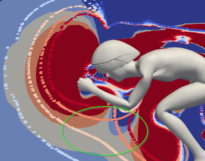
That is what the image shows. Technically, they are not isobar lines, but each line corresponds to 1% difference to mainstream flow velocity. The solid shaded area are the flow velocities of the position shown, the dotted lines are the iso-error lines from a different position.
The image didn’t turn out super easy to read, I can think more if I can do a better visualization of the relative difference between the two positions.
That’s the issue: In the same location relative to what? The bike, your hands, your head? What is the same location if you move one of those?
Depending on where you place the sensor, the calibration factor may change if it’s a big enough change in position. There are best practices to minimize this but it is not an issue.
Example. Place a sensor directly below your hands at 0deg inclination of the extensions. Then incline the extensions by 30deg. Calibration will change
You simply test in the new position and the calibration changes required will be detected and/or calculated. No separate calibration run.
Again, different sensors handle this is more elegant ways than others
When a device is being used properly the concern the OP is raising is not an issue
Not always. Errors due to mismeasured (or unmeasured) wind are systematic, so you can learn something from them. Instead of virtual elevation, I’ve looked at virtual wind.
I rarely completely discard a run. I can learn something from most runs even when they’re noisy. I may not learn a reliable number, but I can often put bounds on what that number is, plus I’ll learn something I can use to improve future runs.
This is all way above my abilities to add anything useful, but is there a reason why they aren’t just mounting the sensor down near the front dropout? It looks like an area with much less variation, unless having half the wheel ahead has an impact too big to avoid by moving the sensor out a reasonable amount?
That’s my bad on misreading the image. Looking at it (correctly, now, I hope) there’s very much bad areas to put an aero sensor, one of which def is near the common area. Almost seems like the best place would be as long of a stick as you can get, but I’m sure that would have it’s own issues (vibration and downstream aero, mainly).
I’m wondering if the best place to mount a sensor might actually be on/near the front axle?
The other question I have is the magnitude of changes required to produce the magnitude of flow velocities shown in the image. It’s possible to fall into a trap of selecting positions that give the highest flow reading at the sensor location, but only if the gain in flow velocity is greater than the aero difference of the new position.
Interesting discussions here. However, some more questions :
Would the dark blue areas, for example the area behind the knees, be best to place an aero sensor?
In what circumstances is ignoring the bicycle justified?
When does the dynamics of pedaling have a significant influence?
And another one before I sleep. I was just amazed about the size of the bow wave in the flow direction. How big is it in the perpendicular direction?
Thanks @marcag for pointing me to the podcast. I had a chance to listen to it yesterday and think about it.
It was great to hear Barney talk about the issue and how they address it. He also mentioned he is active on slowtwitch, so I hope he can weigh in and correct or provide context to any of the statements I am making.
My understanding based on the podcast is that he recommends an out and back procedure and calibrates the wind speed sensor against the ground speed sensor with the assumption that the out and back natural wind component cancels out. So what does this mean:
When we calculate the mean CdA of a test session integrate the equation of motion and solve it for CdA. The part of the equation of motion that deals with aero drag has a mix of wind speed and ground speed in it. When we don’t have a wind speed sensor, we simplify this equation by saying wind speed equals ground speed. Of course, how well this works depends on how close this statement is to being true.
What we do by adding this calibration step is we essentially don’t use the wind speed sensor to measure the mean apparent wind speed (since we replaced that with ground speed in the calibration procedure), the additional information we gain from the wind speed sensor is only about the fluctuation in wind speed.
So right now we have two options:
Use the wind speed sensor to measure wind speed, and incur a confounding error.
Peg the mean wind speed to mean ground speed. Remove the confounder, but also loose additional information on the difference between mean apparent wind and ground speed.
From the dozen or so companies I looked at, I think the aero sensor approach is the most practical solution for day to day use.
I am probably going to get one and run some tests on it. I think the value users get out of the device is not just in the wind speed measurement, but the automated calculation and I think the added ease of use.
What does this mean for practical application:
If you do set up changes close to the sensor (arms or head) you have to use a calibration procedure ever time.
If you do a calibration procedure you are still limited to conditions where you don’t incur significant mean wind speed.
I am not in love with how I titled the post and will change it. I think that criticism is entirely fair. After seeing so many companies not address or address this issue poorly, I made up my mind. Too early as it seems.
Ingmar: As I said, I sometimes look at virtual wind rather than virtual elevation. Especially on courses I’ve used several (many) times before, I have an idea of what the “true” elevation profile is, so rather than turn a power meter into a virtual altimeter, I’m turning a power meter into a virtual anemometer. The point here is that if I’m using an out-and-back, I can see whether the virtual wind in each direction come close to offsetting, or if they’re wildly different. I don’t currently use an aero sensor but, if I did, I’d check the calibration runs to see how variable the virtual winds were. As an aside, I’m sure you know this but not everyone does, wind speed roughly follows a Weibull distribution.
This has been a really interesting thread but when i really cut through it it seems the key takeaways are
Aero sensors need to be “calibrated”
Change in setup being tested can impact calibration factor, therefore may need to be recalibrated.
Miscalibration can meaningfully mess up results so trying to gmhave good “calibration hygene” is important
While calibration error across setups cant be mitigated through more runs and could cause misinterpretation, calibration error within a particular setup can (presumably?) be mitigated through more calibration runs - i.e. if you rerun the calibration many times for the same setup, the mean calibration factor is more likely to be reflective of the true mean. To me this is part of calibration hygene.
Calibration error can also occur due to assumptions/method to set calibration not being valid (example if calibration assumption is wind out = wind back, but this not correct for a given calibration e.g. due to gusty or stochastic wind conditions). More sophisticared approaches could help reduce this and i think there will be a lot of innovation around this in the future. More calibration runs can help mitigate this, as calibration errors due to wind variation get averaged out.
These are limitations, and create a level of “inconvenience” of the sensor, but i can say from my experience testing with an aero sensor is orders of magnitude better than trying to test without one! I think with patience,good protocol, and lota of runs you can test some reasonably granular differences.
Calibration is one potential source of error but we need to be careful to position this as the single limiting factor - power error, crr setting and consistency, allowing for temperature adjusted crr, accurate elevation and simply whether the rider can actually hold a position in a way that their “true” cda is even repeatable with low variation run to run all can make things go awry. Robert always says something along the lines of… all “good” aero tests are the same, but there lots of ways for a test to be “bad”
I’ve read through most but not quite all of the thread and this is definitely the kind of thing I like to think about. I think the process marcag refers to can actually do a pretty decent job at getting to a solution in a practical way. I have a slightly less practical solution that I just thought of that may be more accurate. It requires a stationary wind measuring station set up along the course. At the time the cyclist passes this station on each run, you know the precise speed and yaw angle of the free stream air in relationship to the rider and this can be used to calibrate each run, taking into account how positional and equipment changes affect the upstream pressure gradient (bow wave). You will either have to measure or manually enter the cyclist bearing at the time of passing the wind station. You will need a way to find in the data where the time passing the weather station is, whether by GPS or some other method. It can all be done. Is the added accuracy, cost and setup PIA worth it? No idea.
I was exploring a similar idea to use ultrasonic car parking sensors on tripods every 20m or so. You could build a system for ~$20 each. Ultrasonic wind speed measurement can be extremely accurate over these distances and you could use this wind information. Still, you would need at least 20 of them and its not very practical from a set up perspective.
This is the key question for any of those devices. Both for the customer and the company. Its a tough business to make work.