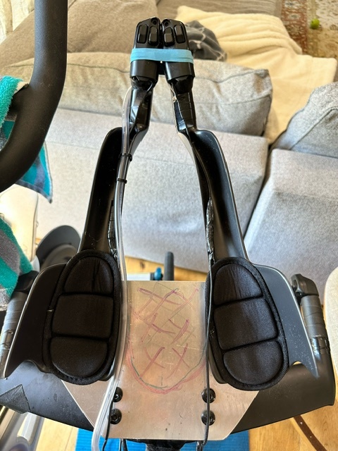
Making my own 20 degree extension adopter. Should I cut the middle open or should I keep it or it doesn’t matter?
Another question, I don’t use BTA bottle since I drink from speedfill, should I add one like Sam long for aero gain?
Making my own 20 degree extension adopter. Should I cut the middle open or should I keep it or it doesn’t matter?
Another question, I don’t use BTA bottle since I drink from speedfill, should I add one like Sam long for aero gain?
From an aero point of view, probably better to cut it, but I’d highly recommend keeping it so that you also keep all your teeth. You have a long moment arm with that extension, and if you trim it I could see a scenario where that plate brakes when you hit a bump or something while riding in aero.
I used 1/4 inch thick 6065 alum and it is less than 5 inch’s long. I kind of doubt I or anyone would be able to bend or break it.
nice work on that!
The one thing everyone seems to forget about with angled extensions is the A part of CdA.
Maybe a BTA would be faster, it could be slower.
Should I trim the mid part draw on pix 1?
I tried filling in that area on a similar project. It was a bit slower when I tested it in the wind tunnel. The guy who was running the tunnel said it isn’t uncommon the increase drag when you are trying to divert air flow.
If you mill out that section, the two sides will not be able to share vertical load (though it will lessen lateral loading/torque on the risers). I’d keep that section to help the load distribution. If you want to drop a bit of weight, mill out a center pocket 1/8" deep on the top side.
Thanks. So I should just trim it?
I tried filling in that area on a similar project. It was a bit slower when I tested it in the wind tunnel. The guy who was running the tunnel said it isn’t uncommon the increase drag when you are trying to divert air flow.
Thanks. So I should just trim it?
I tried filling in that area on a similar project. It was a bit slower when I tested it in the wind tunnel. The guy who was running the tunnel said it isn’t uncommon the increase drag when you are trying to divert air flow.
It’s really individual. Example, Sam Laidlow found covering that gap (with duct tape) was faster. LCB tried it and found it was slower. Both have won the IMWC, so it’s not like they have poor positions as a starting point. We’ve seen similar variability with things like calf sleeves (much faster for me, but test slower on others ).
If you mill out that section, the two sides will not be able to share vertical load (though it will lessen lateral loading/torque on the risers). I’d keep that section to help the load distribution. If you want to drop a bit of weight, mill out a center pocket 1/8" deep on the top side.
One could actually do the deflection calculations on it
Lets say 50lbs live load force per arm, rough calculations:
Single beam (two fully separate pieces, 3cmx5cmx0.63cm) = 0.029cm deflection
Kept as shown in picture One piece, double load, 20cm wide) = 0.00639cm deflection
Max cantilever deflection for live loads is L/180, or 3/180=0.0166cm. Idk if there’s a different standard for vehicles, this is just the standard engineering def. I’d keep the bridge in the middle and keep the extensions under each at least 5cm wide. The real issue is that 1/4" aluminum stock is too thin for this application. Using even just 3/8" would allow a much narrower profile.
Username checks out.
paint it black
.
Hmmm… There is a possibility that leaving it whole is faster aerodynamically, but of course, without testing, you can’t know. It depends a lot on your position and whether this will deflect enough air away from your body to overcome it’s own additional drag or not.
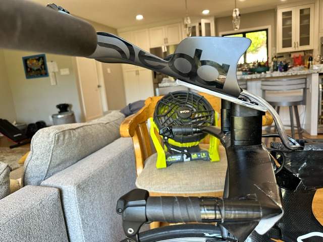
A photo of you on the bike might be useful.
As for strength, remember that going over a pothole or railroad tracks can multiply your force on it several times. I’m not sure what the right standard is, but I would think 4x the weight you normally put on it is not an unreasonable strength target. When I used to design stuff that hung off semi truck frames, 9g acceleration was our design target but the suspension amplified that in certain situations.
If you mill out that section, the two sides will not be able to share vertical load (though it will lessen lateral loading/torque on the risers). I’d keep that section to help the load distribution. If you want to drop a bit of weight, mill out a center pocket 1/8" deep on the top side.
One could actually do the deflection calculations on it
Lets say 50lbs live load force per arm, rough calculations:
Single beam (two fully separate pieces, 3cmx5cmx0.63cm) = 0.029cm deflection
Kept as shown in picture One piece, double load, 20cm wide) = 0.00639cm deflection
Max cantilever deflection for live loads is L/180, or 3/180=0.0166cm. Idk if there’s a different standard for vehicles, this is just the standard engineering def. I’d keep the bridge in the middle and keep the extensions under each at least 5cm wide. The real issue is that 1/4" aluminum stock is too thin for this application. Using even just 3/8" would allow a much narrower profile.
Username checks out.Better than anyone’s. It’s uncanny, usually.
I did the same thing but for a canyon speedmax CF SLX (rim brake) with the same extensions
I used Alu 7075 5mm
It won’t break and material fatigue shouldn’t be an issue BUT it flexes.
It’s noticeable with bumps in the road or if trying to flex the extensions by its end while stationary.
To reduce the flexing I used 2.8mm steel plates between the alu plate and the angled shims.
However my design looks way more flex-prone than yours. Good luck!
Wow! Impressive! Yours is next level. Do you have machines to make this?
I will be using 3/8 (10mm) 7075 once it is delivered.and paint is black.
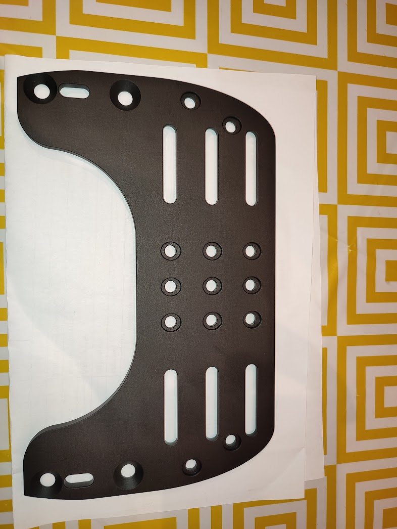
No. I used https://jlc3dp.com/ to do the CNC.
I used
Aluminum 7075Hardcoat anodizing-Black-MatteThe rest as default (ISO 2768 medium, Ra3.2, etc)
There were other services (like pcbway) but I found this was the cheapest.
For the design I used onshape.com (free for personal use and online).
Furthermore here’s the design in case you want to use it as a reference.
A few things:
the bottom is the top. Doesn’t matter. It’s just visual.the 3 slots on each side as based on the ones in the deda plates.the 15 holes in the middle are just in case you want to attach something. The same for single ones on the sidesthe 4 countersink holes are for attaching the plate to the base “towers”. Mine were 174mm apart.the base I used was adjustable in angle with a screw, thus the slot between the countersink holes to access it. You might not need it.when done export as step file
How much was the cost?
I think around 20-25€ plus shipping with EuroPacket (vats and import duties were included).
It took less than 2 weeks from ordering to receiving (Europe).
Overall I’m quite happy with the CNC machining results and for that price it was impossible to find something similar local.