I did state that there is in-house testing done. I never stated that this is purely based on intuition.
I also suggest bringing in other voices, such as the people actually making these bars and risers, such as Edwin of Speedbar, and larger manufacturers who make the base bars. That would help with bias.
There is in- house testing
Bias ?
Jeroen walked away from a manufacturer that can’t ensure safety
Dave is well reputed to put safety ahead of everything
If that’s bias, give me more bias.
Let us innovate … safely.
- Shoes - safety risk (hazard x likelihood of event) level?
- Disc or deep rimmed wheels - safety risk level?
- Helmet shapes - meets recognised safety standard - desperate reaching for ‘fairing’.
- Frame tube shapes - safety risk level?
- Cantilevered cockpit fairings - unknown safety risk level
Whataboutery
Exactly, i don’t worry about the extensions, i worry about the lever that is being created on the base bar, stem and fork as unit all together.
And even more when you hit pot holes, etc.
The bar / stem we tested in combination with the reach hardware failed not at the extensions but at the cross section between bar and integrated stem.
Jeroen
1 Like
Exactly, that’s what doesn’t make sense. So this fairing blade is legal but a duct tape between the aerobars is illegal.
I understand home-made bottle holders are rejected as they can fall and endanger the rest, but a tape without any kind of structural demands is basically the same as this ones.
So the conclusion is if you buy it is alright, if you make it not.
Coming back to the data
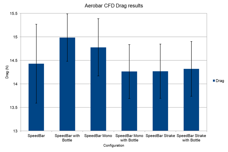
Are we saying that Trevor’s setup at last Kona, with a bottle, is slower than without ? (2 first bars)
Can you translate to watts at say 45km/h ?
1 Like
While this is obviously a fairing, if you made it lower and hollow it would be a good candidate for a drink system shape. Suddenly the line blurs…
1 Like
But the question is : “does it actually provide aero benefit ?”
If yes, maybe, if no, there are ways of carrying hydration that do provide a benefit
I printed it to see if the concept works for me
Well actually the question under the World Tri Rules is not "does it actually provide aero benefit?" but is it “designed to reduce resistance”?
10.2. Protective screens, fuselages, fairings, or any other device or material added or blended into the structure destined or reduced [(typo btw, should be “designed to reduce”] resistance to air penetration are prohibited. Aerodynamic assemblies and protuberances on the head tube or elsewhere are prohibited.
Same same under IM Rules, but clearer imho.
5.03 (b) Protective screens, fuselages, fairings, or any other devices . . . added or blended into the structure with the intent to reduce (or having the effect of reducing) resistance to air penetration are prohibited. Aerodynamic assemblies and protuberances on the head tube or elsewhere are prohibited.
This looks very like an “aerodynamic assembly” to me; and with clear intent to boot.
However a hydration reservoir shaped like this (a litre maybe, as proposed by Tim) has legs. @Nick_wovebike would be right behind this innovative opportunity.
Why are bike bottles designed with ‘bluff body’ bases? Just for aid station convenience?
No, actually the question is “is there any aero benefit”. If yes, chase whatever excuse you want to come up to allow it. If no, move on to something that does provide a benefit.
3 Likes
Or it might be “Is there a way we could market this as aero” without having the slightest idea it actually is in the real world
4 Likes
Unfortunately that is more the rule than the exception in this wild world we live in
And I don’t mean this about the product above. I think Ed & Co should be applauded for releasing their data and idea.
Two test sessions done. Now I have to properly build a BTA to test that angle. All for fun, I have something else I am testing in parralel.
2 Likes
There was in-house testing done. That’s how we know. I’ve written multiple times that there was in house testing.
I agree that real world fatigue testing is a requirement for strength testing. FEA and static tests don’t capture the stresses experienced outdoors. I’ve also seen FEA not predict in field failures.
I’ve written about suggestions for improved ISO testing above and I was transparent about the testing I do on my products.
How much does one of 100k cycle tests cost to do ?
Some pricing: https://biketesting.com/?ref=escapecollective.com
Wow. $400 for a fatigue test ?
Edit : ok, $1300 to $1700
with this not being my product, I’m not comfortable saying anything publicly other than about my own tests for my own products.
What I can say is that we have done some pretty extensive testing on some of these aluminum parts, and it is wild how the computer simulations, and even incredibly demanding static tests cannot predict what happens when you’re outdoors and going over bumps for several hours. The 200,000 repetition fatigue test is the best that I have for that, but I would argue that the moment of force and impulse needs to be greater to simulate the suddenness of impacts while going down the road at 50 km/h.
I’d be really curious how the fatigue calculations were performed. It should be pretty straightforward to model an aerobar setup to predict the stresses that occur and get a life approximation. Should still test, but I’d hope that testing pretty quickly becomes model validation rather than finding new failure modes. What software is used? Where do you get fatigue failures in these parts? Primarily with 3d printed aluminum?