Hi All,
Several times now, I've been asked to describe a protocol for Aerolab or other virtual elevation testing. To make it easier to find, I've put the word "Platypus" in the subject (and now, also in the thread itself). So here, without further ado, are some rules for running virtual elevation tests:
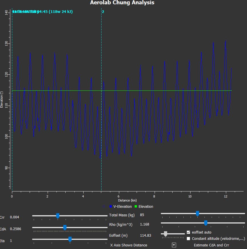
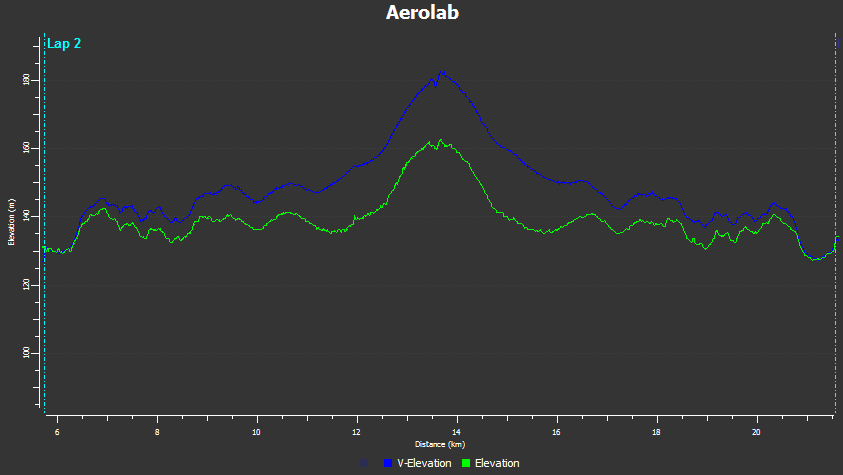
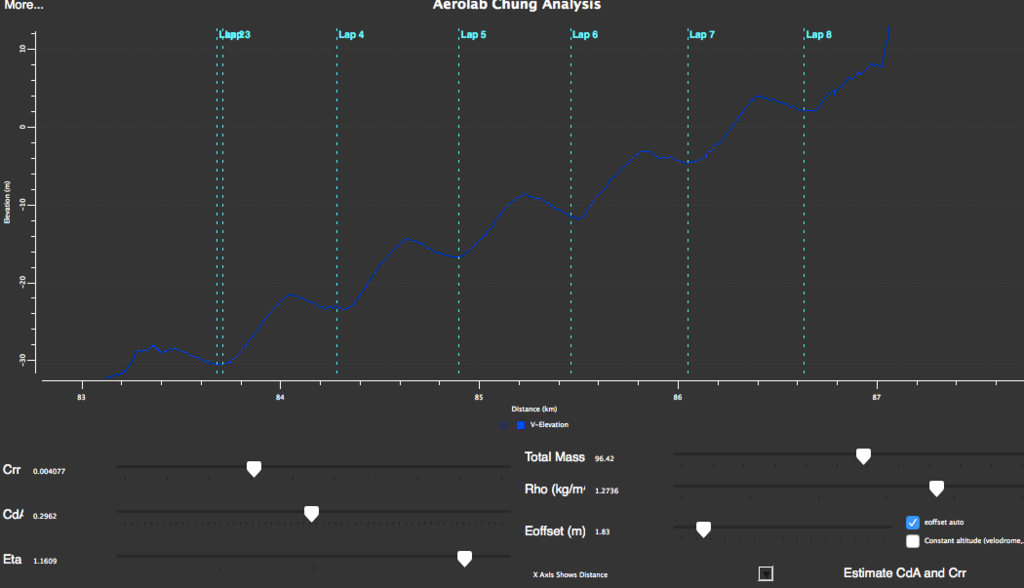
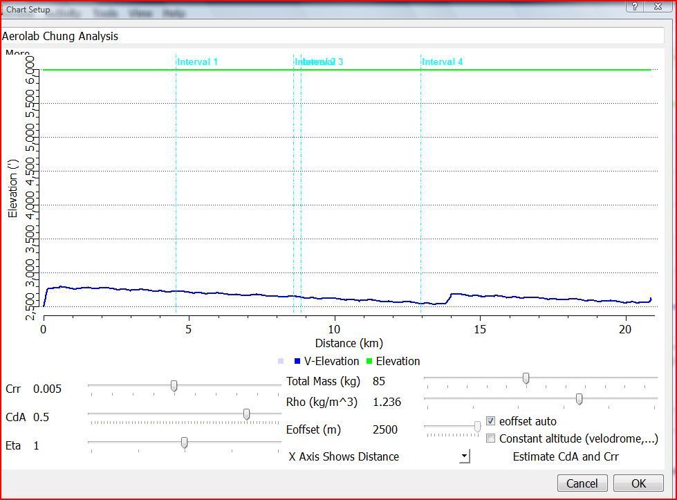
Here is what a properly executed VE test looks like. Here are more good tests.
Let's continue to improve this thread into a real VE reference so that we can simply refer new VE people to it by saying "Oh, just search for the Platypus thread".
Cheers!
AndyF
bike geek
Several times now, I've been asked to describe a protocol for Aerolab or other virtual elevation testing. To make it easier to find, I've put the word "Platypus" in the subject (and now, also in the thread itself). So here, without further ado, are some rules for running virtual elevation tests:
- First and foremost: be safe!!!!! Scrap the run if you encounter danger. It's just not worth it.
- Weigh yourself as accurately as possible. And use a well-calibrated power meter.
- Do the tests on a windless day -- it will save you a lot of headaches.
- Use a loop, out-and-back, or half-pipe protocol. They should be relatively short (300m-1.5km).
- for loops, run at least 5 laps, each at different speeds. More laps on a short course is better. - Choose a course which has some elevation change, and on which you (safely) won't have to use your brakes.
- If you can, survey your course properly. GPS and altimeter elevation data isn't really that good. That's why it's more important to rely on loops and out-and-backs than to rely on raw elevation ride data.
- Strive to get repeatable results first. Don't start optimizing position until you understand the data you're getting. Ride on the same equipment and in the same position for at least 3 or 4 full sessions, taken on different days. You'll learn what factors affect your results.
- Did I mention not to use the brakes? That.
- Determining the air density is really important. If you start getting serious about this, then invest in one of these: http://www.onetreeknoll.com/...ductCode=PI-W-4250BT
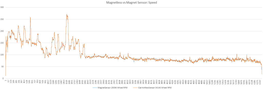
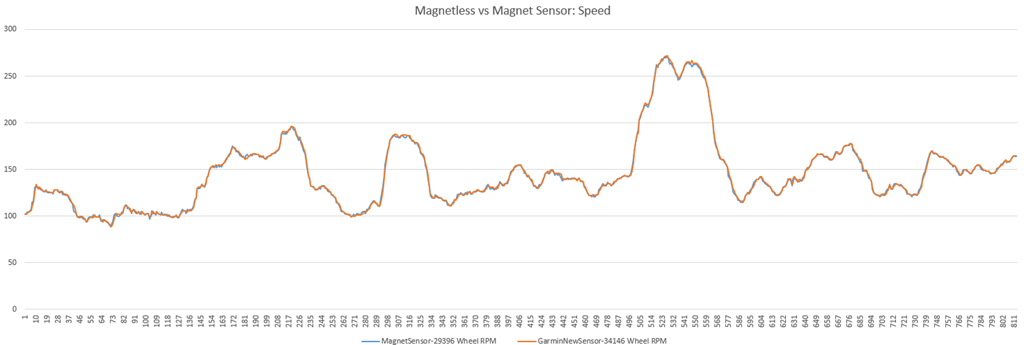
- If you have a GPS-enabled head unit (eg. Garmin Edge 500), disable the GPS -- it will pollute your speed data. Make sure you have a separate speed sensor (eg. Garmin GSC-10) for that.
- Turn off anything that looks or smells like "Smart Recording". You need simple, clean data sampling.
Here is what a properly executed VE test looks like. Here are more good tests.
Let's continue to improve this thread into a real VE reference so that we can simply refer new VE people to it by saying "Oh, just search for the Platypus thread".
Cheers!
AndyF
bike geek


 [/url]
  [/url]
  [/url]